Asembly of Magni 6 Mini
This guide provides clear, step-by-step instructions for assembling the Magni 6 Mini robot.
Note
If any parts are missing, refer to the Magni BOM for ordering details. For unavailable items, contact Ubiquity Robotics support.
[TODO: We will add the link to the Magni 6 BOM order details here.]
Build Requirements
Before starting, ensure all required components are available. The tables below list the Magni 6 Mini Bill of Materials (BOM). Use specified BOM items to avoid assembly issues, though simiral components may be substituted if necessary.
Screws BOM |
|
|---|---|
BOLT M2,5x14 ((8.8) Zn) ISO 7380 |
5 |
BOLT M2,5x10 ((8.8) Zn) ISO 7380 |
2 |
BOLT M2,5x8 ((8.8) Zn) ISO 7380 |
17 |
BOLT M2x14 ((8.8) Zn) ISO 7380 |
2 |
BOLT M2x5 ((8.8) Zn) ISO 7380 |
8 |
BOLT M2,5x5 ((8.8) Zn) ISO 7380 |
2 |
BOLT M4x8 ISO 7380 |
10 |
WASHER 2,7 (Zn) DIN 125 |
22 |
WASHER 4,3 (Zn) DIN 125 |
6 |
SPACER L=12 F_M2,5 |
4 |
PCB PUSH PIN WITH SPRING |
2 |
Other BOM |
|
|---|---|
BASIC |
1 |
TOP COVER |
1 |
FRONT COVER |
1 |
FIREWALL |
1 |
BATTERY HOLDER |
1 |
HEAT SINK |
1 |
MOTOR WHEEL |
2 |
CAMERA MODULE 3 V8 |
2 |
5.5 x 2.1 mm DC POWER CHARGER |
1 |
SINGLE BALL ROLLER BEARING |
1 |
RUBBER TYRE |
2 |
ON/OFF ROCKER SWITCH |
1 |
LIDAR |
1 |
RASPBERRY 5 |
1 |
MOTOR BOARD |
1 |
BATTERY |
2 |
SONAR |
15 |
COVER CAP |
16 |
LIDAR |
1 |
RUBBER PAD |
1 |
MOTOR WHEEL |
2 |
RUBBER SOCKET |
1 |
Assembly Intructions
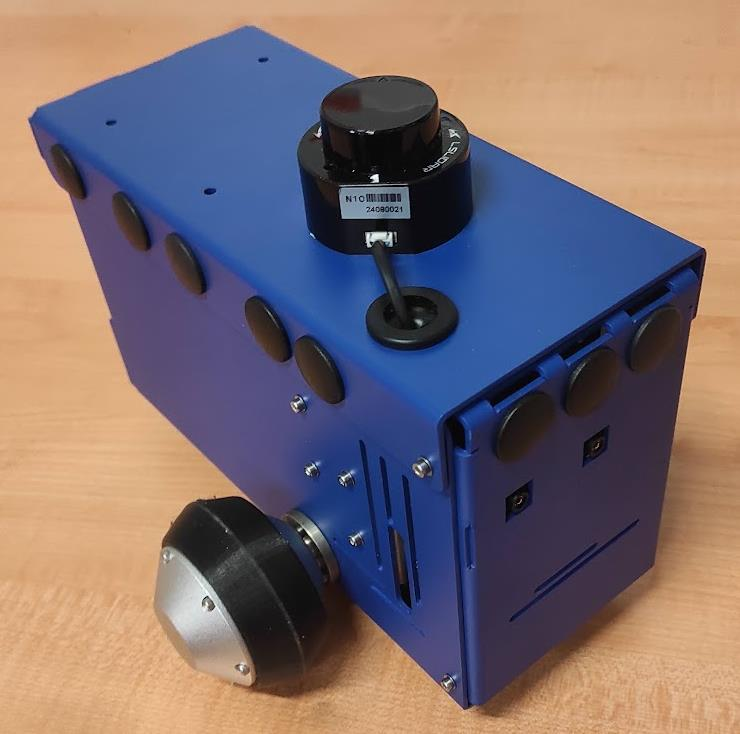
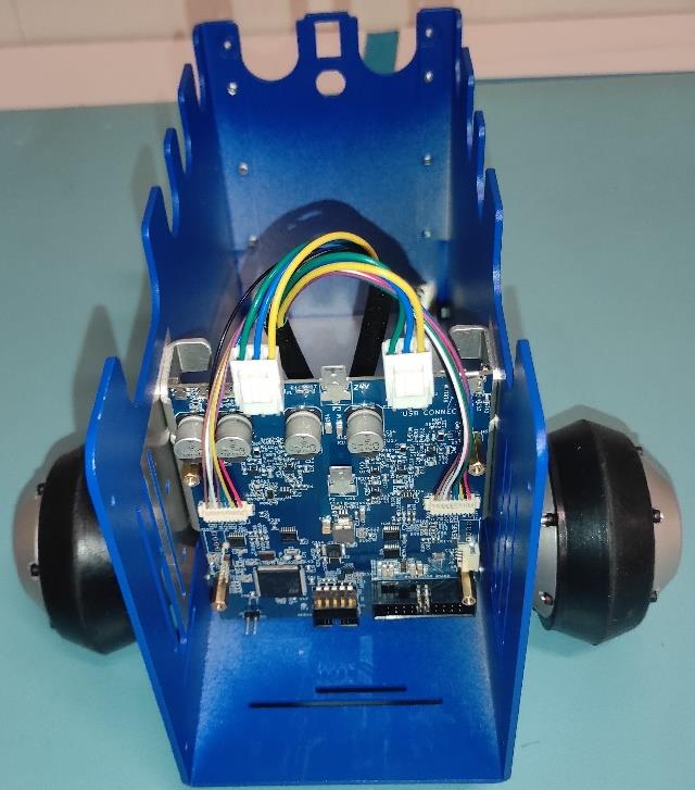
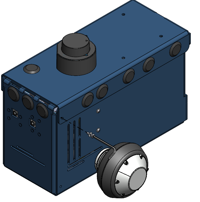
Final Assembly Preview
Step-by-Step Assembly
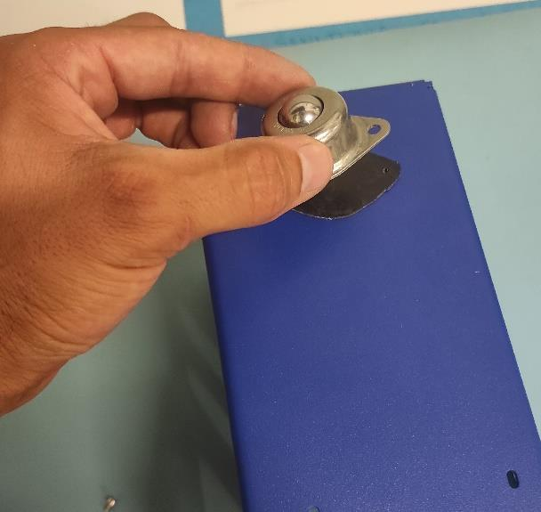
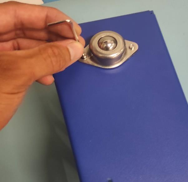
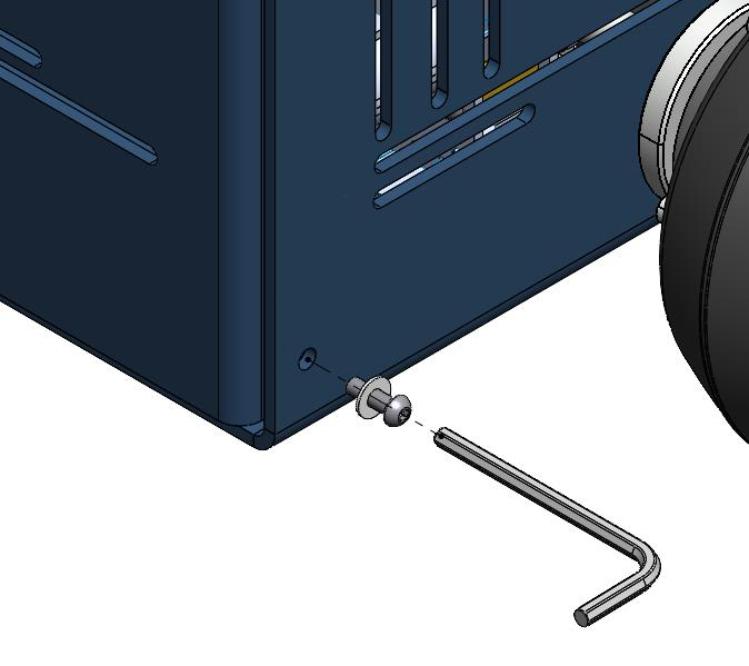
Attach Roller Bearing to Base
Secure the SINGLE BALL ROLLER BEARING and RUBBER PAD to the BASIC sheet metal part using 2x BOLT M2x5 (8.8) Zn) ISO 7380. Tigthen genrly with a hex key using two-finger pressure to avoid overtightning.
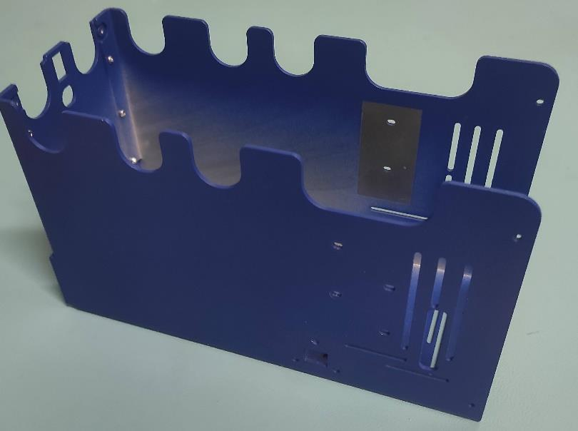
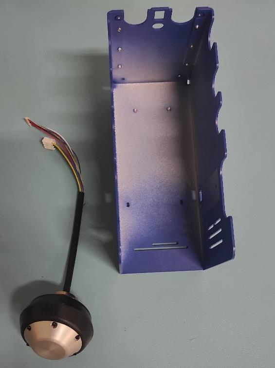
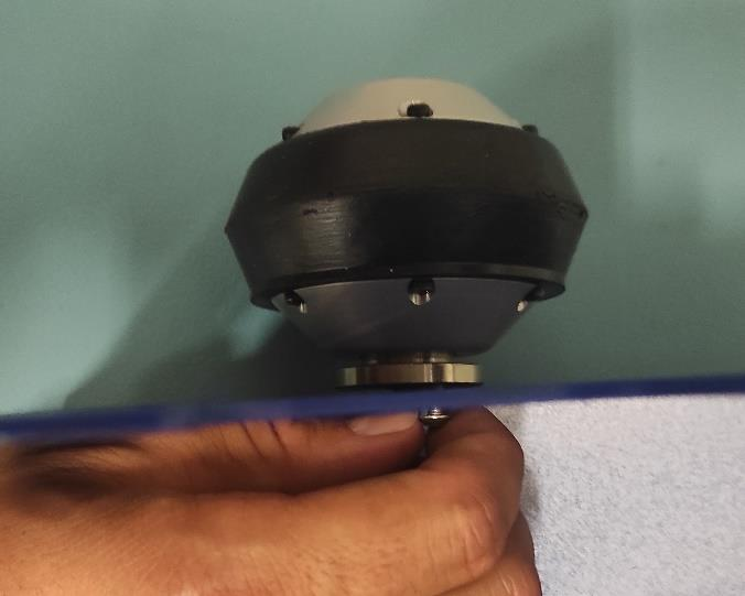
Prepare Motor Wheels
Take MOTOR WHEEL and BASE.
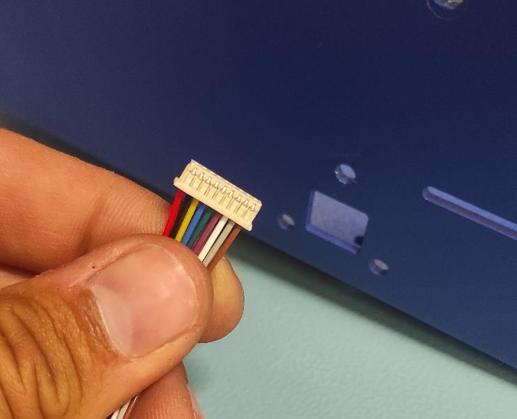
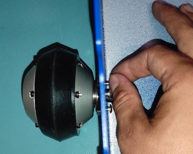
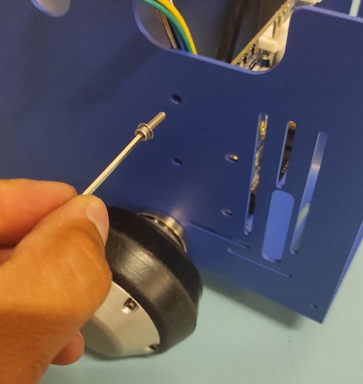
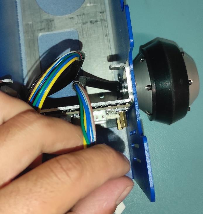
Insert Motor Wheel Connector
Slide the small MOTOR WHEEL connector diagonally through the base opening.
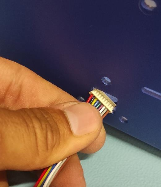
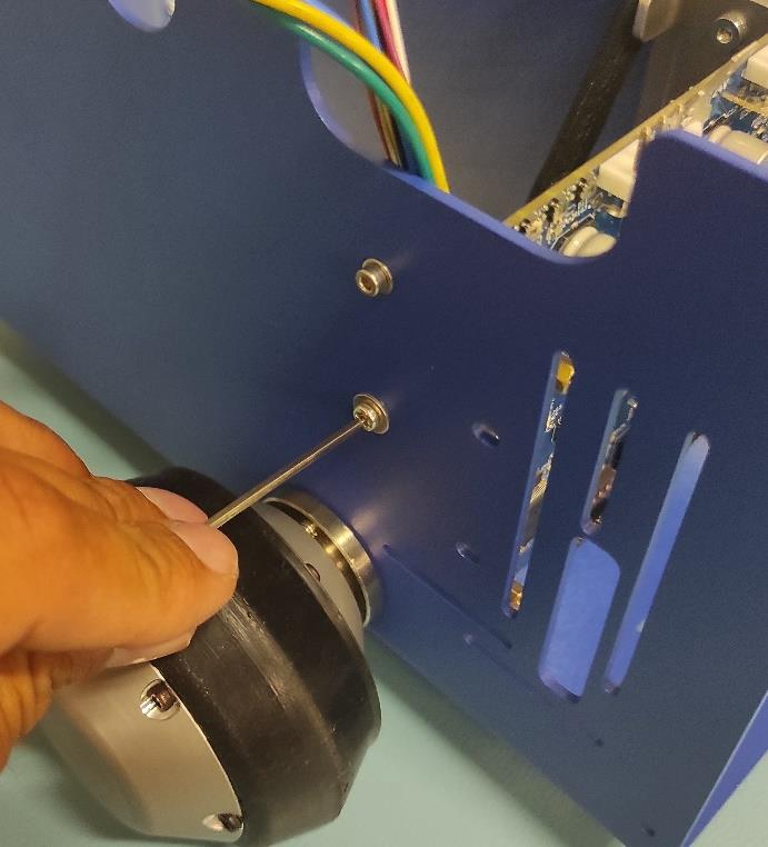
Insert Second Connector
Push the second MOTOR WHEEL connector through the opening, ensure the orientation is correct.
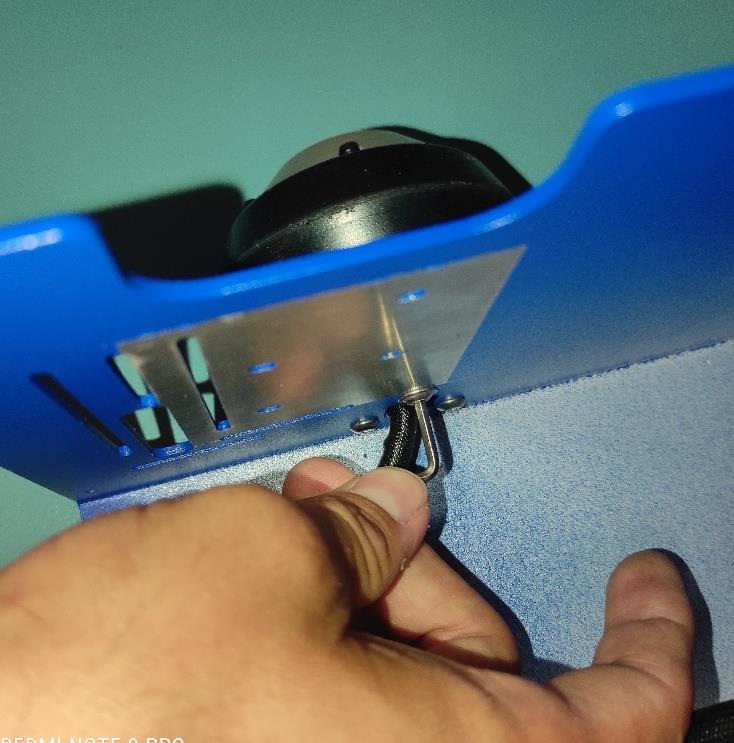
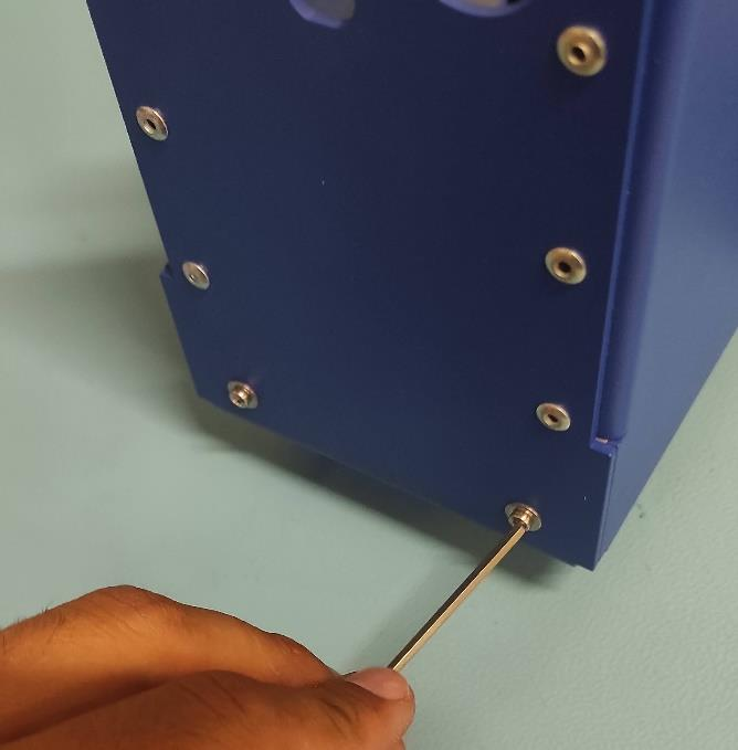
Secure Motor Wheel
Use 3x BOLT M4x8 ISO 7380. Thread each bolt lightly by hand. Tilt the base so the wheel faces up, then the second and third bolts.
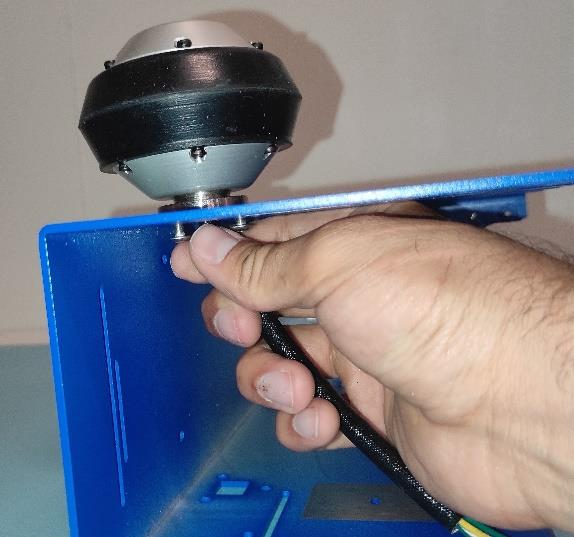
Tighten Motor Wheel Bolts
Fully tighten all three bolts with an Allen key.
Repeat for the Other Side
Follow steps 2-6 for the second MOTOR WHEEL.
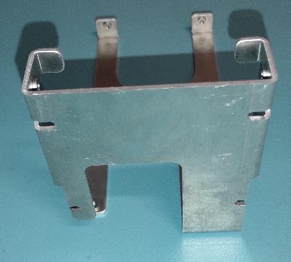
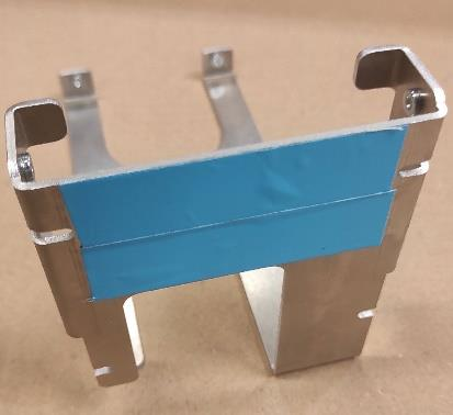
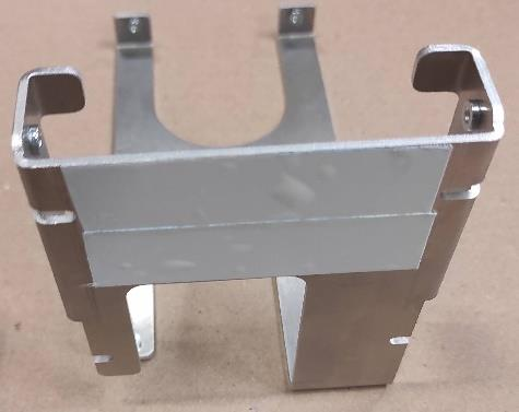
Prepare Firewall
Cut two 70x20 mm strips of double-sided thermally conductive tape. Apply to FIREWALL and remvoe protective film.
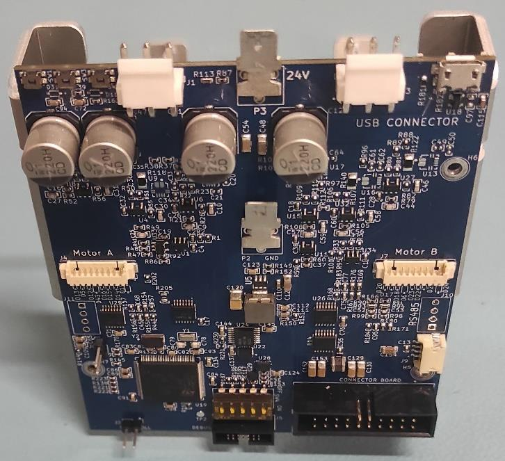
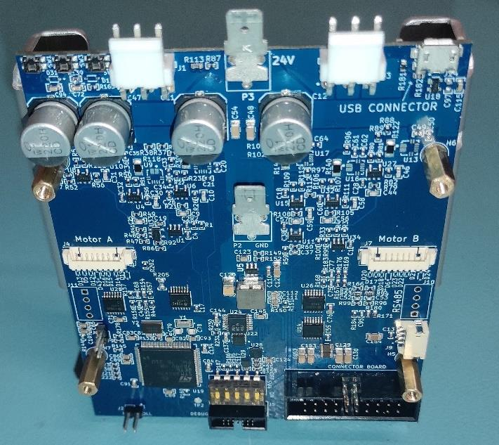
Mount Motor Controller Board
Press the MOTOR BOARD onto the tape, aligning mounting holes with FIREWALL slots.
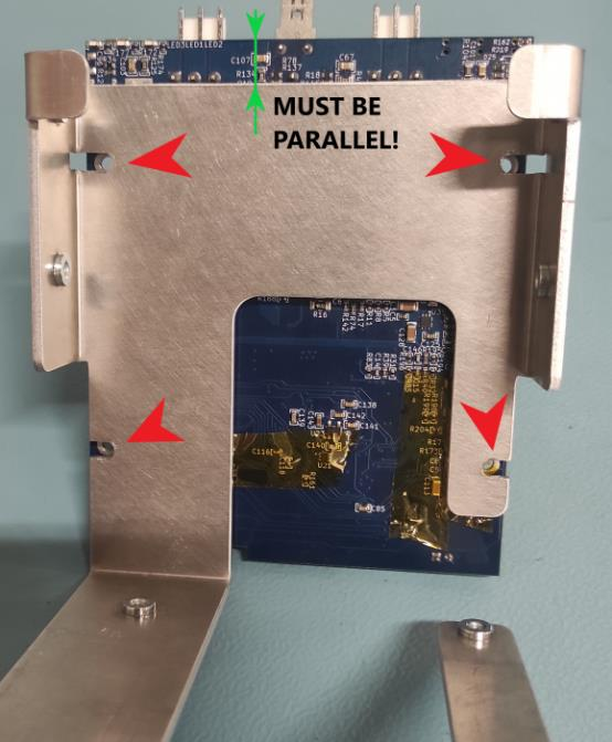
Secure Firewall to PCB
Use Spacer L=12 F_M2.5, WASHER 2.7, and BOLT M2.5x8 ((8.8) Zn) ISO 7380 to attach FIREWALL to PCB.
Warning
Do not tighten fully!
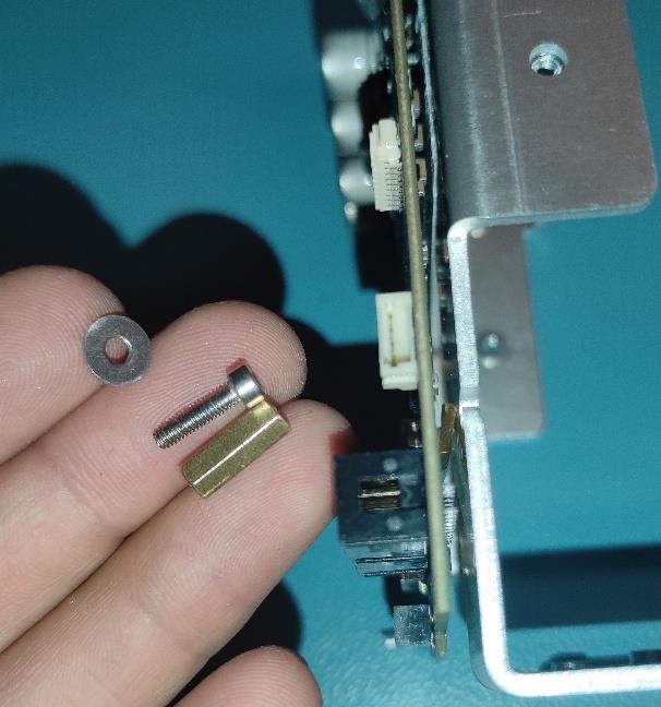
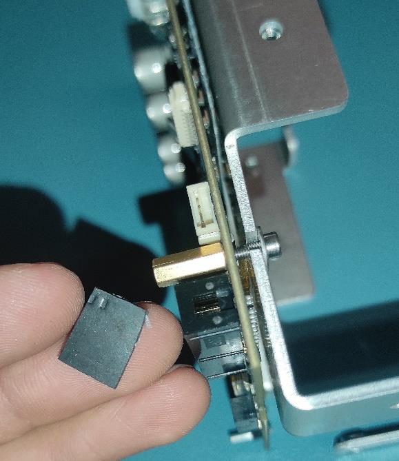
Add Rubber Pads
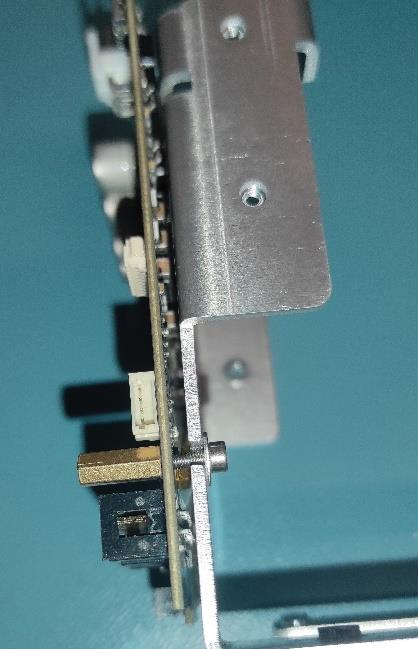
Place a 15x10x3 mm RUBBER PAD between FIREWALL and MOTOR BOARD at the PCB edge to ensure the components are parralele to one another. Tighten bolts gently with two-finger pressure. Repeat for the other side.
Note
The PCB and FIREWALL should be PARALLEL!
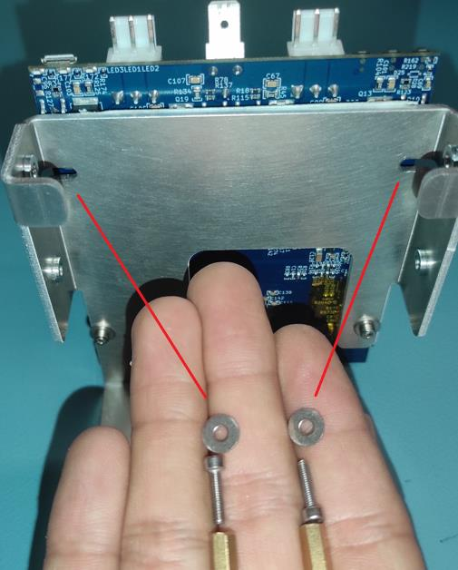
Secure Top Side of Firewall
Use SPACER L=12 F_M2.5, WASHER 2.7, and BOLT M2.5x8 ((8.8) Zn) ISO 7380 to gently tighten the top side of FIREWALL and PCB.
Important
Check that the components are in parralel to one another.
Install Firewall Assembly
Slide the FIREWALL assembly into the BASE.
Secure Firewall Bottom
Use BOLT M2.5x8 ((8.8) Zn) ISO 7380, WASHER 2.7 to firmly tigthen the bottom of FIREWALL to BASE.
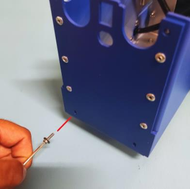
Secure Firewall Side
Use BOLT M2.5x8 ((8.8) Zn) ISO 7380, and WASHER 2.7. Thread lightly with an Allen key.
Note
Final tightening will be done after full assembly.
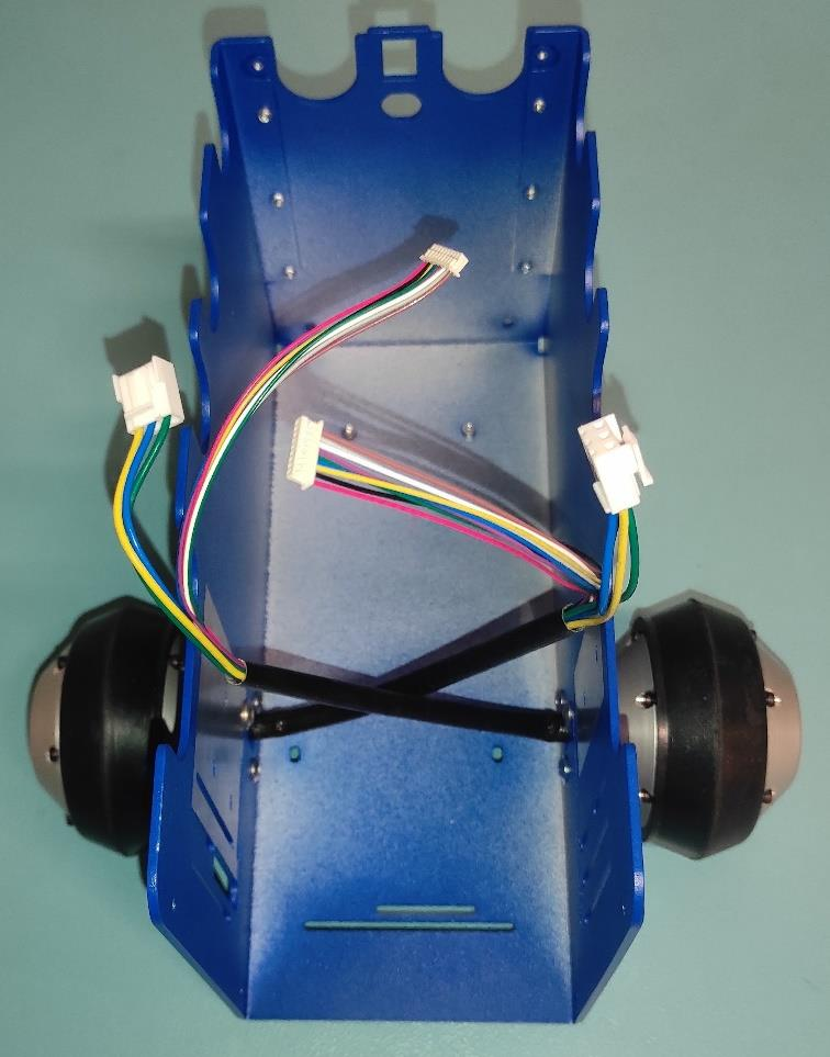
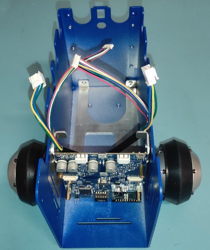
Connnect Left Motor Wheels
Attach the small left MOTOR WHEEL connector to the left side of the MOTOR BOARD. Be sure to turn it correctly.
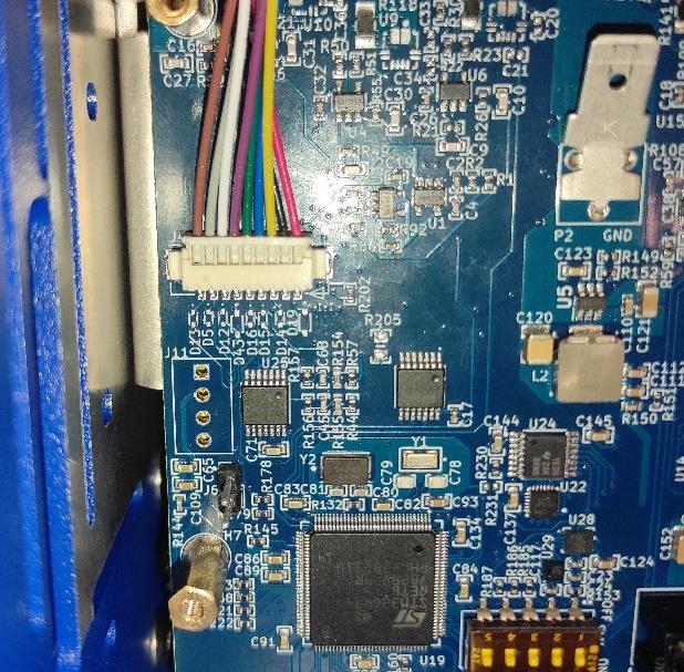
Connect Large Left Motor Connector
Attach the large left MOTOR WHEEL connector to the MOTOR BOARD, orienting and routing the wire as shown.
Note
Left wheel connectors attach to the left side of the MOTOR BOARD. And the right wheel connectors to the right side.
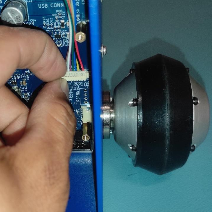
Route Rigth Motor Wires
Ensure right-side wiring matches the pictures below.

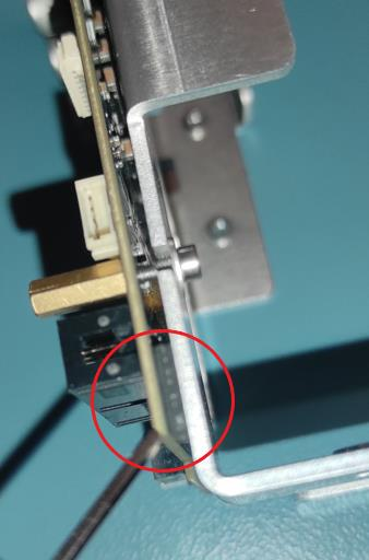
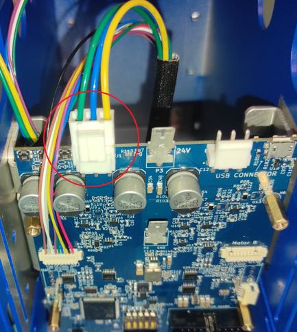
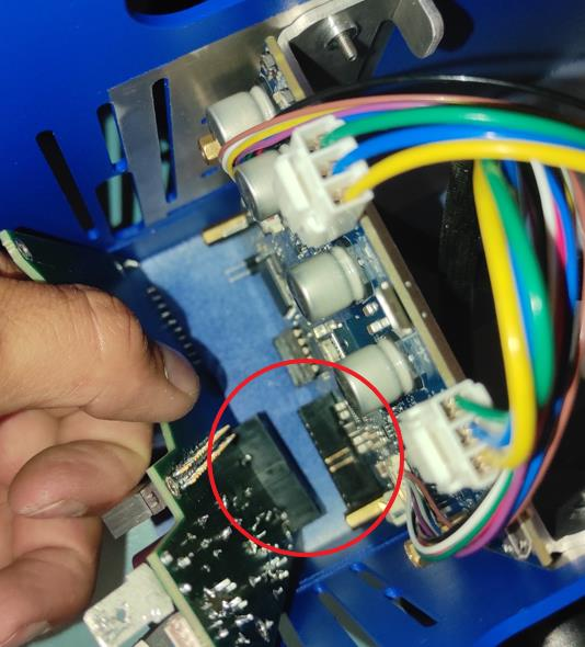
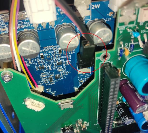
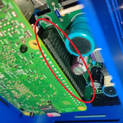
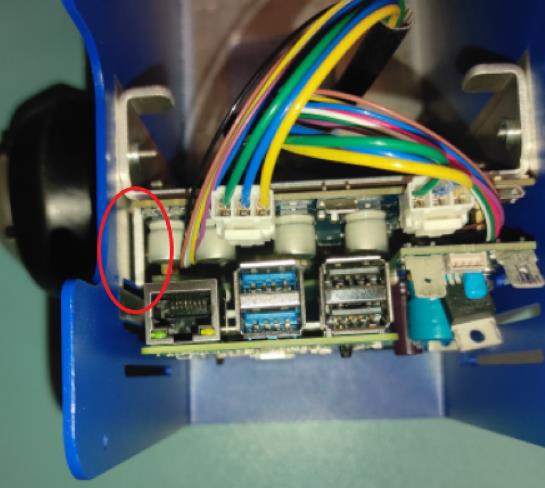
Connect Connection Board
Gently push the CONNECTION BOARD connectors (red circle) into the MOTOR BOARD until fully engaged.
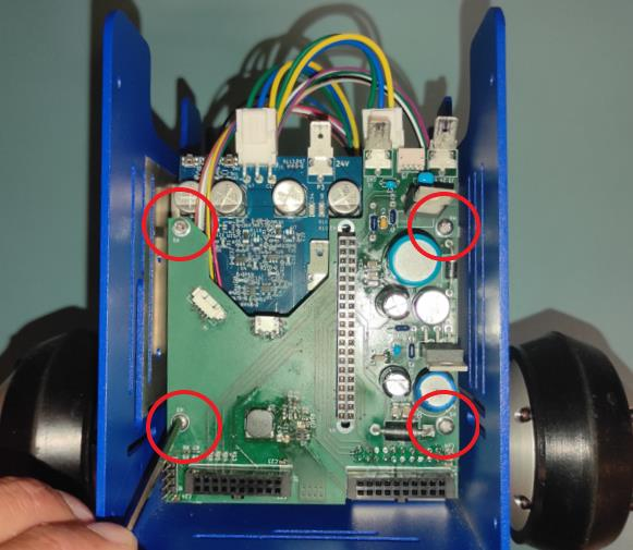
Secure Connection Board
Use 4x BOLT M2.5x8 ((8.8) Zn) ISO 7380 to fasten the CONNECTION BOARD to the MOTOR BOARD through standoffs.
Note
Tighten them carefully.
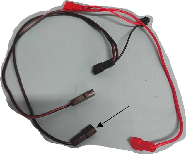
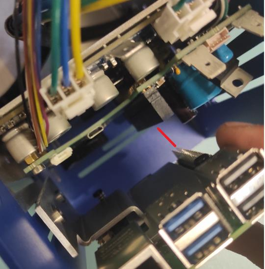
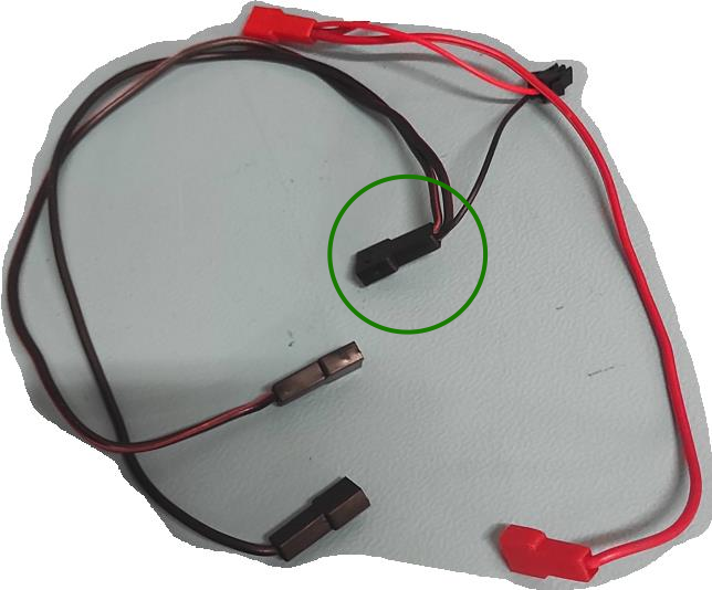
Connect Ground Wire
Attach the ground female spade crimp terminal from the wire harness to the ground pin on the MOTOR BOARD.
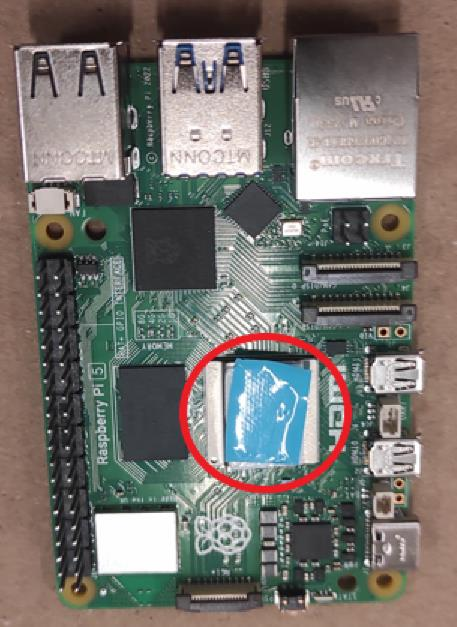
Prepare Rasbperr Pi 5
Cover the Raspberry Pi 5 CPU with double-sided thermally conductive tape and remove the protective film from the tape.
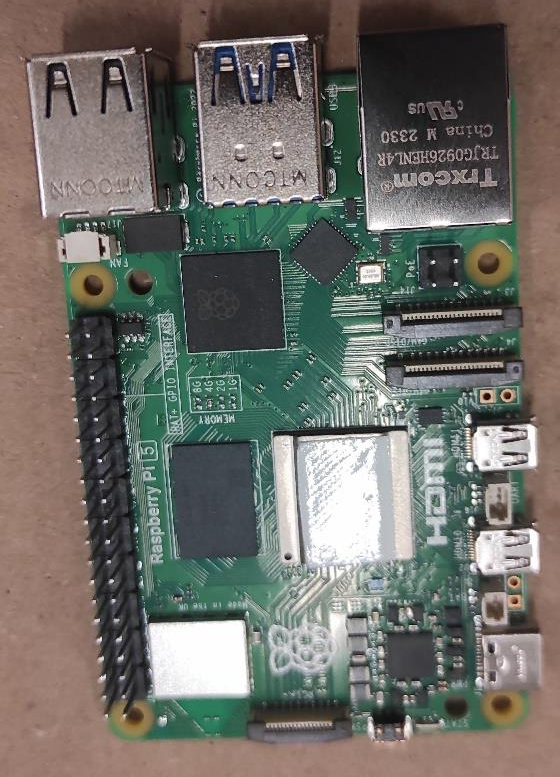
Gather Heatsink Components
Take HEATSINK, 2x PCB PUSH PIN WITH SPRING, and the previosly prepared Raspberry Pi 5.
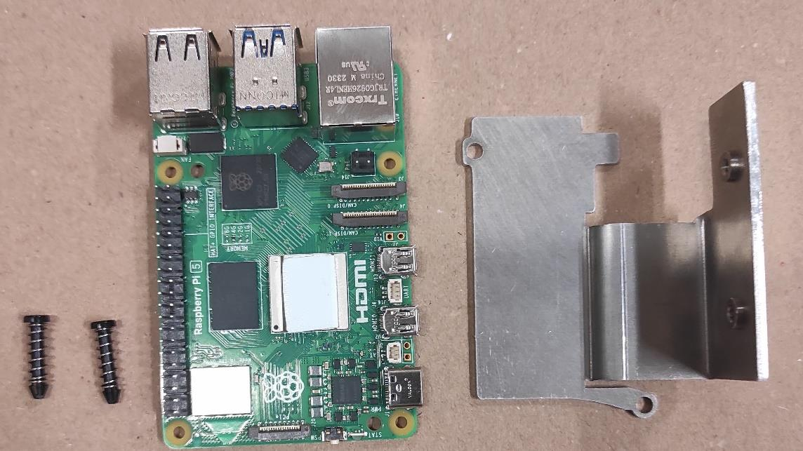
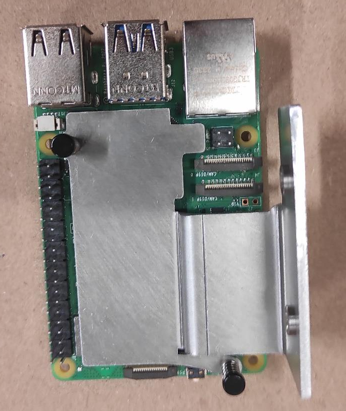
Attach Heatsink
Position HEATSINK on Raspberry Pi 5 as shown in the picture and secure with 2x PCB PUSH PINS WITH SPRING.
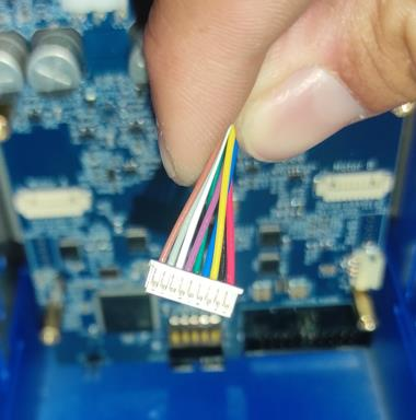
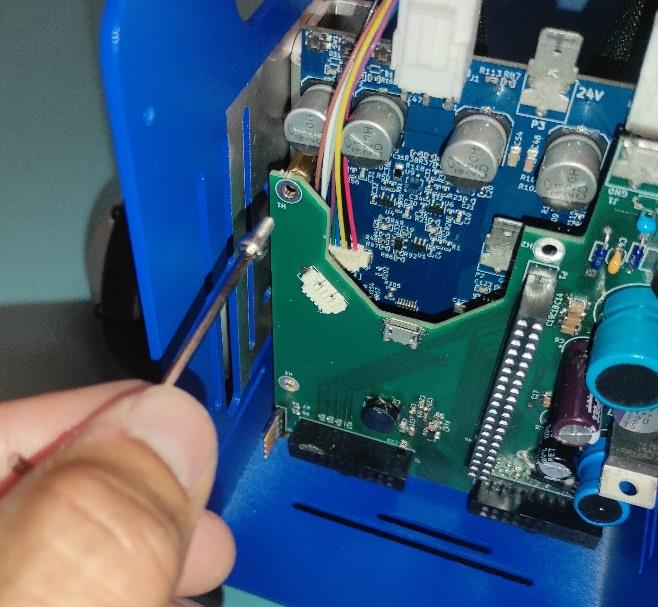
Connect Raspberry Pi to Connection Board
Connect the Raspberry Pi HAT & GRIPO INTERFACE connector together with CONNECTION BOARD as shown in the picture.
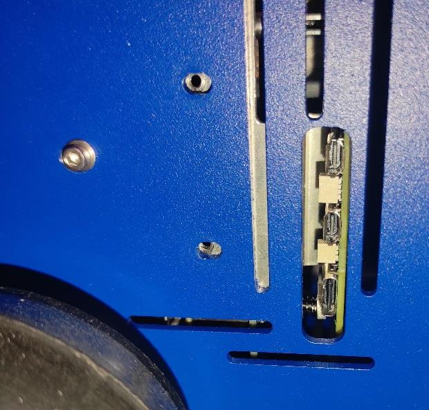
Secure Raspberry Pi (Part 1)
Ensure the HEATSINK contacts the BASE metal sheet and USB/Ethernet ports are accesible. Use 1x BOLT M2.5x8 ((8.8) Zn) ISO 7380 with WASHER 2.7 and tigthen gently.
Warning
Do not tighten the screw fully.
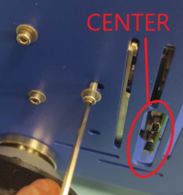
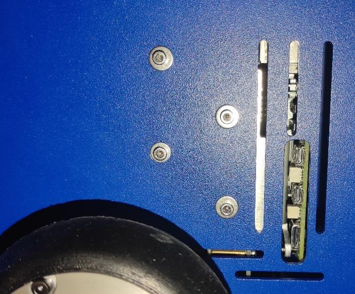
Secure Raspberry Pi (Part 2)
Insert another BOLT M2.5x8 ((8.8) Zn) ISO 7380 with WASHER 2.7. Press Raspberry Pi 5 to center USB/Ethernet ports in the slot, then tigthen gently.
Secure Firewal Bottom
Use 2x BOLT M2.5x8 ((8.8) Zn) ISO 7380 with WASHER 2.7 to fasten FIREWALL to BASE at the bottom of the robot.
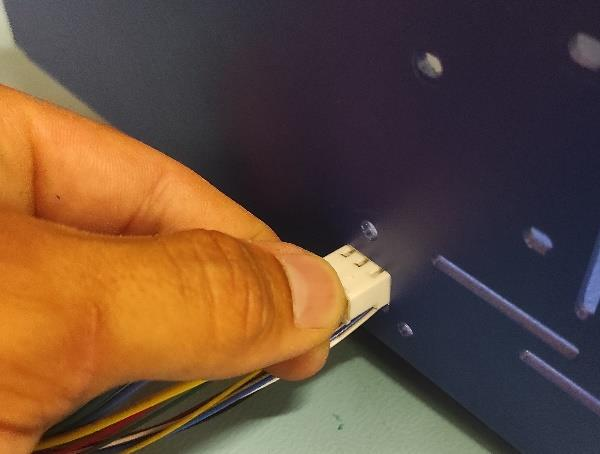
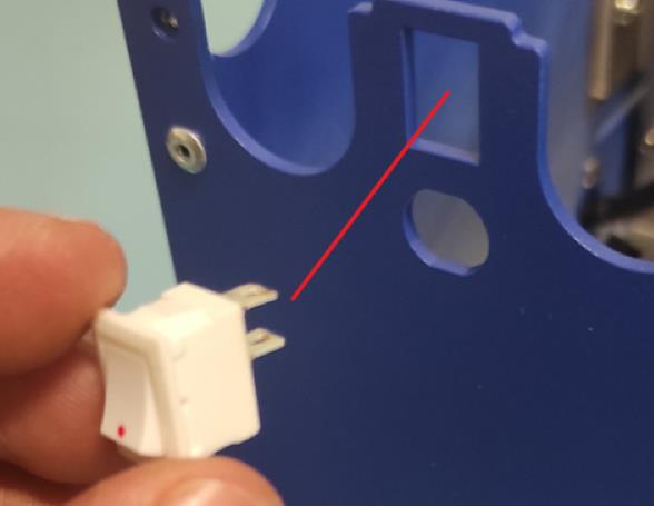
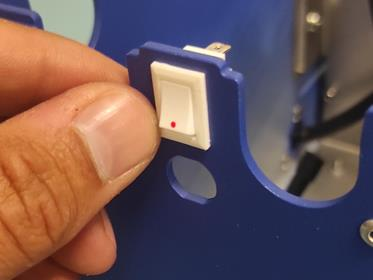
Install On/Off Switch
Press the ON/OFF ROCKER SWITCH into the slot. Make sure you follow the picture bellow.
Important
Pay attention to the position of the dot on the switch. The dot needs to be on the bottom.
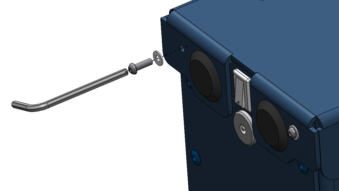
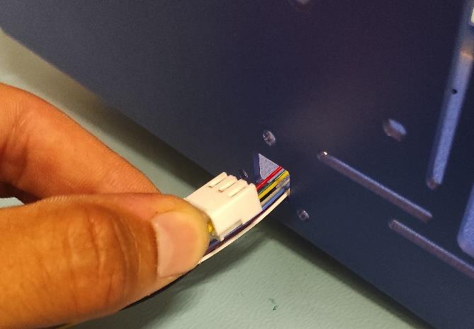
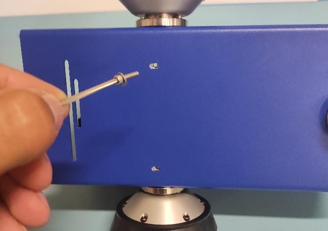
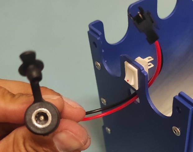
Install DC Power Charger
Push the 5.5 x 2.1 mm DC POWER CHARGER through the opening as shown in the picture below.
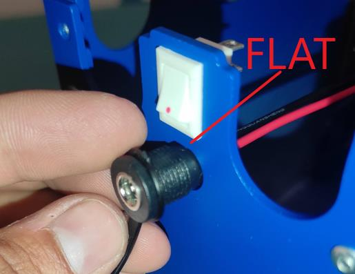
Align DC Charger
Align the first flat part of the charger with the slot and push through the sheet metal as shown in the picture below.
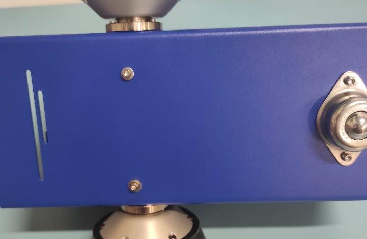
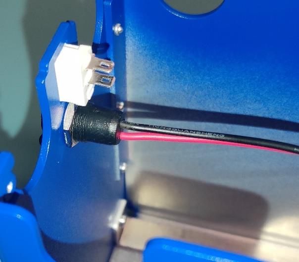
Secure DC Charger
Attach the nut to the charger connector.
Tighten DC Charger
Ensure that the connector is properly aligned as shown in the picture. Then hand-tighten the nut.
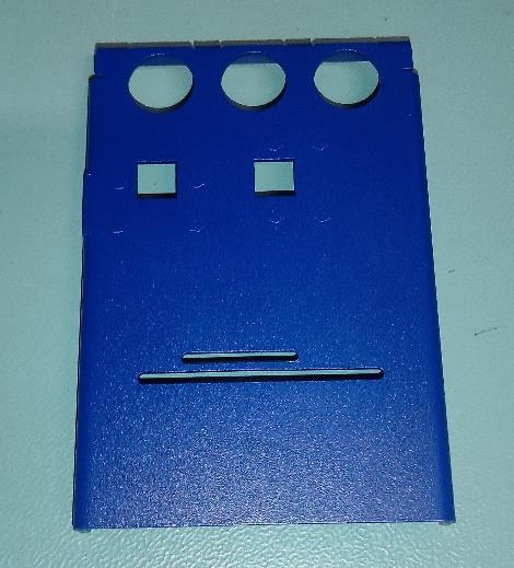
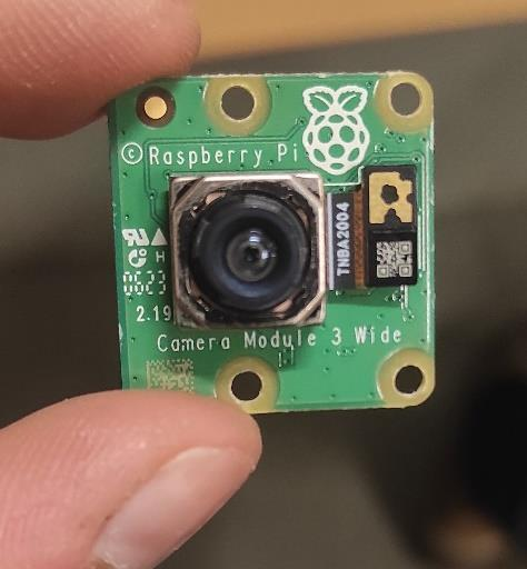
Prepare Front Hatch
Take FRONT COVER of the Robot and CAMERA 3 WIDE.
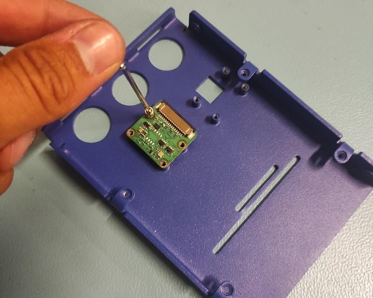
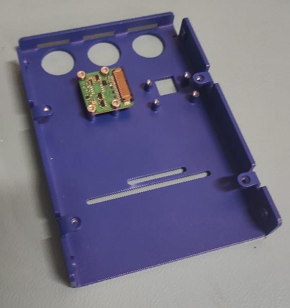
Attach Camera to Front Cover
Use 4x BOLT M2.5 ((8.8) Zn) ISO 7380 to secure the CAMERA to the FRONT COVER. Tigthen with Allen key using two-finger pressure.
(OPTIONAL) Second Camera
Use 4x BOLT M2.5 ((8.8) Zn) ISO 7380 to attach a second CAMERA to the FRONT COVER, tigthening with two-finger pressure. The robot ships with one camera. You may add a second or reposition the first for a different angle.
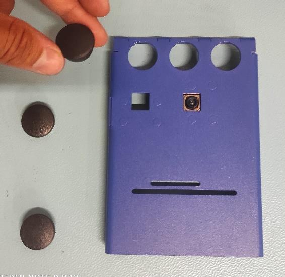
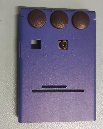
Install Cover Caps on Front
Press COVER CAPS firmly into the FRONT COVER by hand.
Tip
Use steady hand pressure to secure the caps.
Warning
Try to avoid pinching your fingers while pressing the caps. As this may lead to some pain.
Preparing Top Cover and LIDAR
Just like for the FRONT COVER, insert COVER CAPS into the TOP COVER. Secure LIDAR to the TOP COVER with 2x BOLT M2x14 (8.8 Zn) ISO 7380, tigthening gently with two-figer pressure.
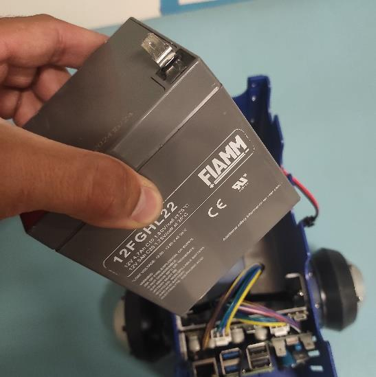
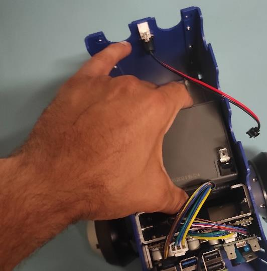
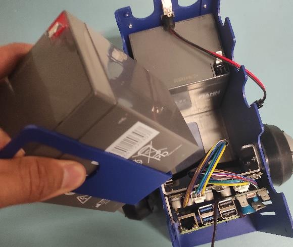
Install First Battery
Position the first BATTERY in the BASE according to the pictures below. Pay close attention to its orientation.
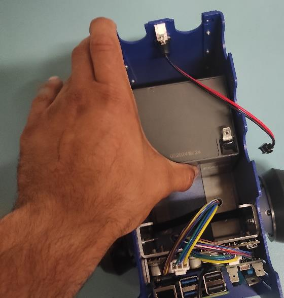
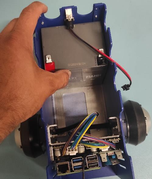
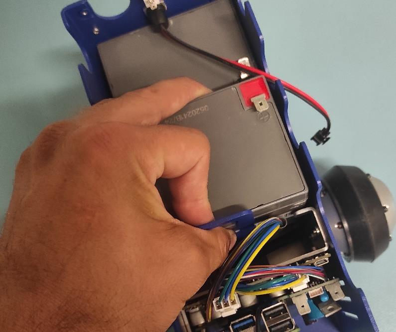
Install Second Battery
Use the BATTERY HOLDER to secure the second BATTERY in the BASE as shown in the picture.
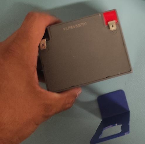
Properly Adding the Second Battery
Be careful with the wires.
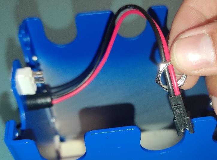
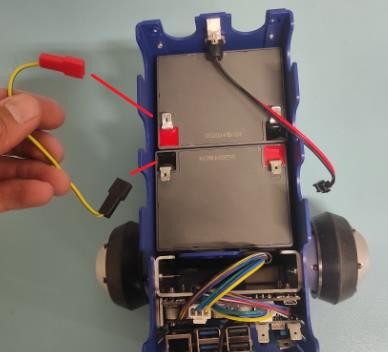
Connect Batteries in Series
Attach the yellow-green wire: red connector to the RED spade of the first battery, black connector to the BLACK spade of the second battery.
Note
Red connector from the wire goes to the RED spade of the first battery. Black connector of the wire goes to the black spade of the second battery.
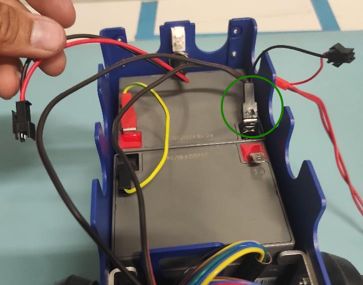
Connect Black Spade to Battery
Take the wire harness and connect the black female spade terminal to the negative battery pin as shown in the picture. Press it in firmly.
Connect Black Spade to Ground
Grab the only free black female spade connector and attach it to the GND pin on the CONNECTOR BOARD as shown in the picture.
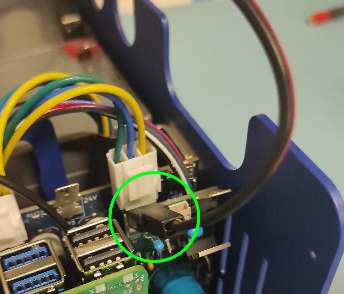
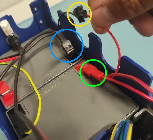
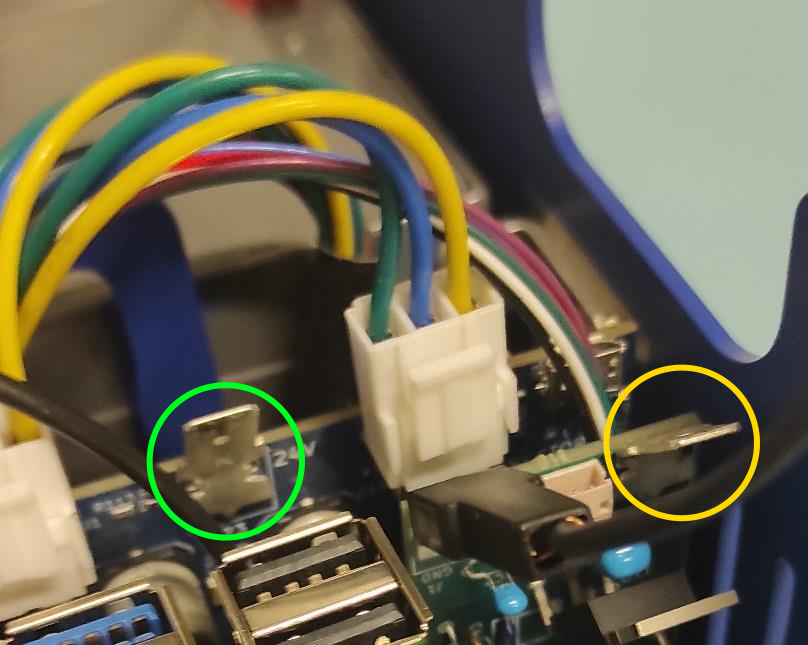
Connect Red Spade and Charger
Attach the short RED spade connector to the positive battery pin (green circle). Connect the charger connector to the 5.5 x 2.1 mm DC POWER CHARGER (yellow circle). Finally connect the BLACK spade connector to the negative spade of the first battery (blue circle).
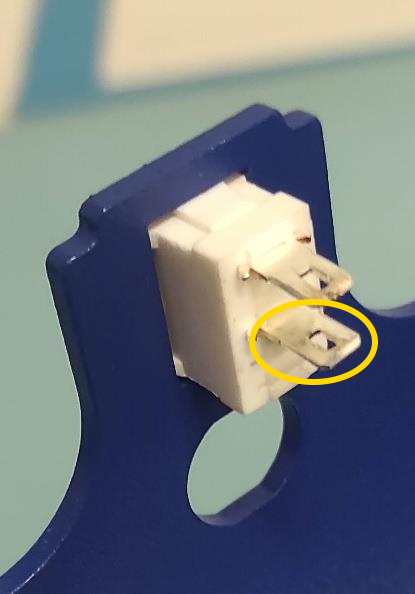
Connect Red Spade to Switch
Attach the remaining red spade connector to the upper pin of the ON/OFF switch.
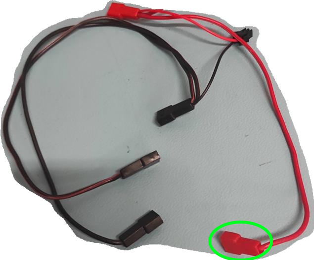
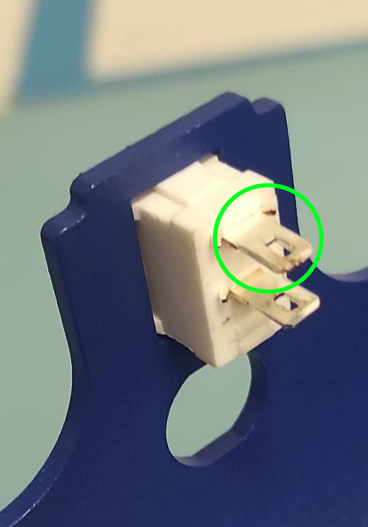
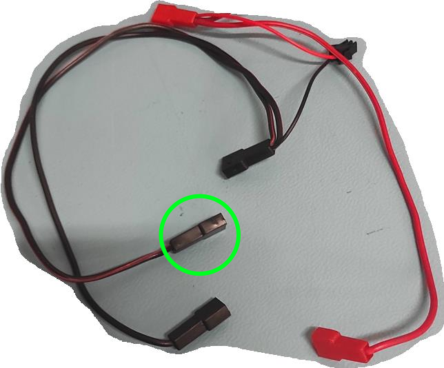
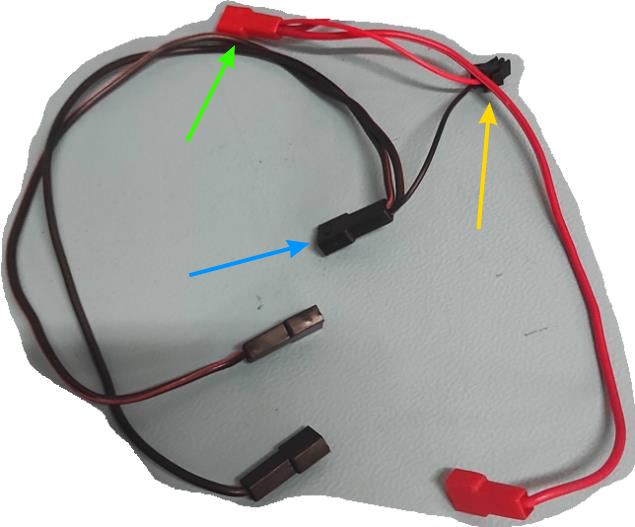
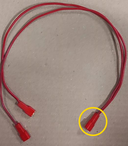
Connect Second Wire Harness
Use the wire harness with 3 red spade connectors. Attach the split connector (yellow circle) to the bottom pin of the ON/OFF SWITCH.
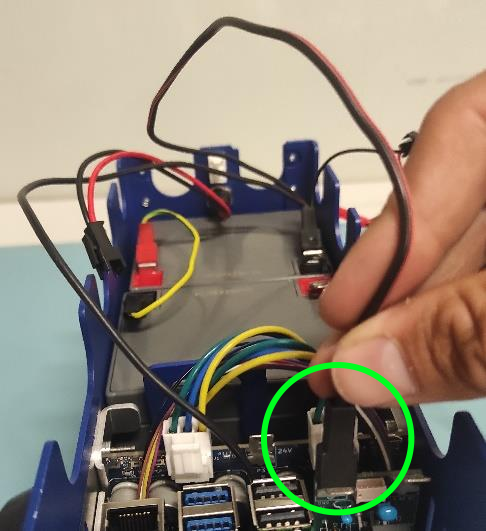
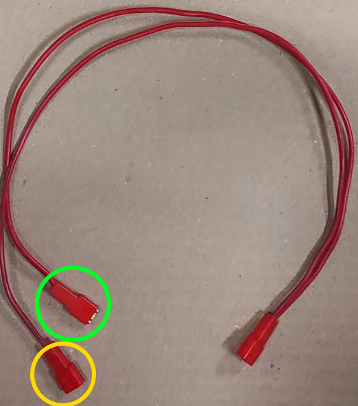
Connect Remaining Spade Connectors
Attach on red spade connector to the 12V pin on the CONNECTION BOARD and the other to the 12V pin on the MOTOR BOARD.
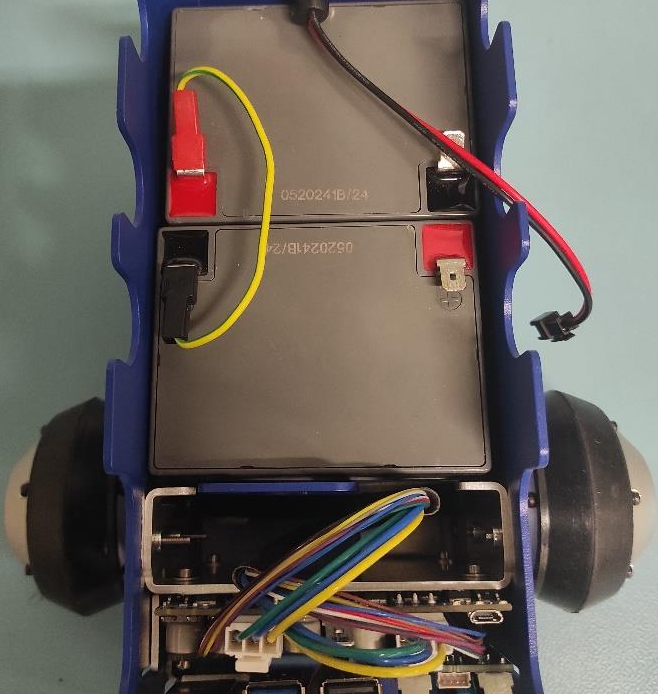
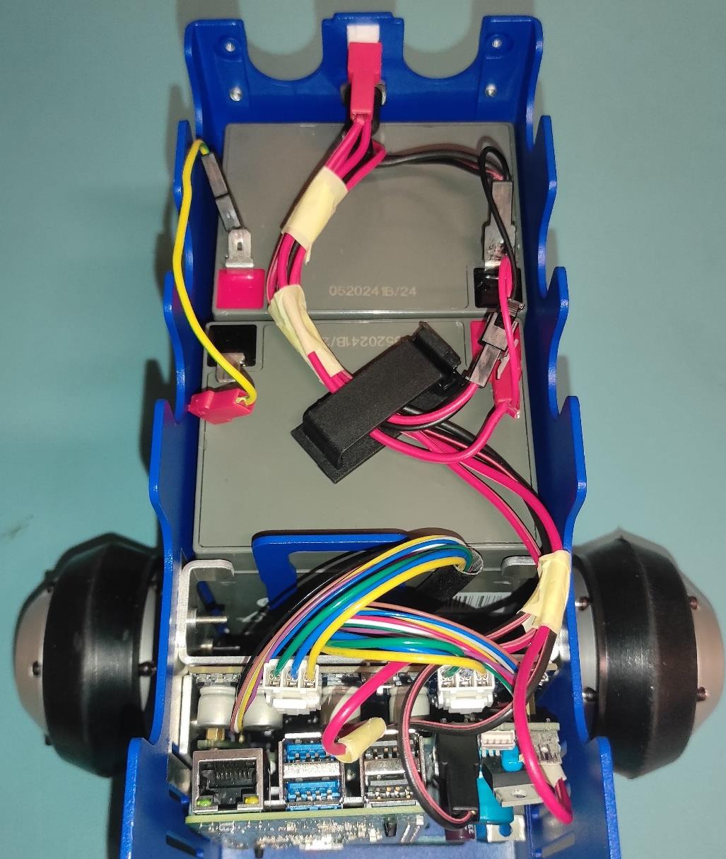
Verify Wiring
Ensure all spade connectors are firmly attached. Route wires as shown.
Important
Double-check that all connections (all pins are firmly connected).
Note
UPDATE of the WIRE ROUTING is coming soon.
[TODO: Add image here without the wires being taped/secured to the second battery.]
Attach Top and Front Covers
Position TOP COVER and FRONT COVER. Use 2x BOLT M2.5x10 ((8.8) Zn) ISO 7380 with washers, tigthening with two-finger pressure. Fully tigthen with an Allen key once aligned.
Secure Front Cover Bottom
Use BOLT M2.5x8 ((8.8) Zn) ISO 7380 with WASHER 2.7 to tigthen the bottom of the FRONT COVER with two-finger pressure.
(OPTIONAL) Top Cover Securing
Use BOLT M2.5x8 ((8.8) Zn) ISO 7380with WASHER 2.7 to secure the TOP COVER. Tigthen lightly with two-finger pressure. This step is optional
Note
This step is optional, as the cover’s weight may be enough to keep itself shut.
Tip
If you are opening and closing the TOP COVER repeatedly then we suggest to avoid this step.
[ FIXME: This should be secured from the other side. I think. ]